1.Project Overview
An aquaculture project is located in Hekou District, Dongying City, Shandong Province. Each pond measures approximately 30 m × 30 m × 5 m (Figure 1). It is constructed of reinforced concrete with a concrete strength grade of C30 and a water resistance grade of P6. The aquaculture water used is slightly acidic, requiring the waterproofing material used in the pond to be both acid- and salt-resistant. The surface of the waterproofing layer must be regularly cleaned of residual contaminants. The project's water seepage limit is 2 L/(m²·day), and the waterproofing level is Class II.

Figure 1 Project real scene
2.Waterproofing Design
The original waterproofing design for the aquaculture ponds used a two-component polyurethane waterproofing coating as a base layer and a spray-coated polyurea waterproofing coating as a top layer. However, due to construction and foundation deformation, some of the aquaculture ponds had developed extensive cracking on the base surface (Figures 2-3). This did not meet the original design requirements for the waterproofing coating, and the surface treatment was difficult and expensive. Therefore, the design was revised to utilize a 1.5 mm thick cement mortar and a 1.2 mm thick thermoplastic polyolefin (TPO) waterproofing membrane (Type L, with fiber backing). The membranes were wet-laid over large areas, creating a fully bonded system (Figure 4). The overlapped edges of the membranes were hot-air welded. After the project was completed and water was stored, the waterproofing effect was excellent.

Figure 2 Extra long crack

Figure 3 Negative eye defect
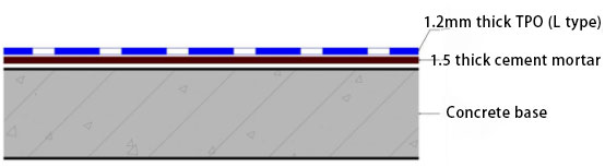
Figure 4 Schematic diagram of waterproofing layers
2.1.Fiber-Backed TPO Waterproofing Membrane
The TPO waterproofing membrane selected for this project is a rollable, fiber-backed thermoplastic polymer waterproofing sheet made from ethylene and α-olefin polymers using advanced extrusion technology. This membrane meets the performance requirements of GB 27789-2011, "Thermoplastic Polyolefin (TPO) Waterproofing Membrane." Its key chemical resistance indicators are shown in Table 1. Its volumetric abrasion loss (DIN abrasion method) at 5 N is 105 mm³.

Table 1 Chemical resistance performance indicators of TPO waterproof membrane with fiber backing
The main performance characteristics of this membrane are as follows:
1) It contains no plasticizers and offers excellent resistance to heat aging and UV rays, preventing deformation, aging, or cracking even after prolonged exposure.
2) It offers excellent tensile, tear, and puncture resistance.
3) It boasts strong thermal welding capabilities, fast welding speeds, high seam peel strength, excellent system integrity, and convenient installation and maintenance.
4) It has a smooth, non-fading surface, is stain-resistant, easy to clean, is chlorine-free, chemically resistant, recyclable, and environmentally friendly.
2.2.Cement Mortar
The performance indicators of cement mortar refer to the requirements of CECS 199-2006, "Technical Specifications for Polyethylene Polypropylene Membrane Composite Waterproofing Projects," as shown in Table 2.

Table 2 Main performance indicators of cement mortar
3.Construction Technology
3.1.Material Preparation
Main Material: TPO waterproofing membrane (Type L, with fiber backing); Auxiliary Materials: Polymer cement mortar, beading, screws, sealant, etc.
3.2.Substrate Requirements
1) The subsurface should be solid and free of hollows, looseness, or sanding.
2) The subsurface should be flat. Flatness should be checked using a 2-meter straightedge. The gap between the straightedge and the subsurface should not exceed 5 mm. Gradual variations are permitted, but should not occur more than once per meter.
3) Local depressions should be repaired and leveled with polymer cement mortar, and protrusions should be smoothed with a chisel.
4) Internal corners should be formed into straight arcs or 45° bevels using 1:3 cement mortar. The arc radius R should be ≥ 50 mm and the bevel side length L should be ≥ 50 mm. External corners should be polished to create a rounded transition.
3.3.Construction Process
Prepare the matching cement mortar → Test-lay the TPO waterproofing membrane → Lay the TPO waterproofing membrane → Overlap the membrane → Finish the joints → Quality inspection and repair → Overall acceptance → Protect the finished product.
3.4.Key Operation Points and Technical Requirements
3.4.1.Preparing the cement mortar
Based on the mortar dosage, add an appropriate amount of water at a water-cement ratio of 0.4-0.5:1. Slowly add cement and the matching instant adhesive powder while stirring. Use an electric mixer to stir for at least 5 minutes. Once the mixture is thoroughly stirred and becomes a gel, let it sit for a while before use. The cement mortar should be prepared and used throughout the construction process. The amount of adhesive powder added is approximately 5‰ of the cement.
3.4.2.Test-Laying the Waterproofing Membrane
Spread the membrane on the base surface to release internal stress. The short sides of adjacent membranes should be offset by at least 500 mm.
3.4.3 Laying Waterproof Membrane
For flat surfaces, apply cement mortar while simultaneously laying the TPO waterproof membrane. For vertical surfaces, apply the membrane pre-slurry and then scrape the mortar onto the base surface (Figures 5-6). Immediately compact and air the membrane after installation. During installation, ensure that the cement mortar does not contaminate the overlap area of the membrane.

Figure 5 Pre-slurrying of the fiber backing surface

Figure 6 Facade construction renderings
3.4.4 Overlapping Membrane
Overlapping membranes are welded using hot air welding. Overlapping can be performed 48 hours after the completion of large-surface membrane construction.
1) Hot Air Welding Equipment Selection: Surface joints are welded using an automatic hot air welding machine. Detailed joints, local repairs, or vertical overlaps are welded using a handheld hot air welding gun in combination with a silicone rubber roller.
2) Key Points for Hot Air Welding Machine Operation:
① Before large-surface construction, the optimal welding temperature should be determined based on the project site's temperature and humidity. A peel test must be performed. After the weld has completely cooled, the membrane should be cut into 20 mm wide strips and peeled.
② The overlap width of TPO waterproofing membranes should be ≥ 80 mm, and the effective weld width should be ≥ 25 mm.
③ After completing seam welding, immediately remove the automatic hot air welding machine nozzle from the joint to avoid burning the membrane.
④ Use a silicone roller to press all joint intersections to ensure a continuous seal for the hot air weld.
3.4.5 Finishing
After the overall large-surface waterproofing application is complete, the membrane should be finished.
3.4.6 Joint Inspection
After the welds have cooled, use a flat-blade screwdriver to inspect all welds to ensure there are no leaks. If defects are found, repair them with a handheld welding machine. After the membrane is laid and sealed, inspect the overall surface quality, overlap quality, local joints, and finishes. Any defects should be repaired immediately. Inspection methods include:
1) Visual inspection to ensure a uniform, shiny molten metal coating is present along the weld edge;
2) Mechanical inspection: Use a flat-blade screwdriver or hook to gently poke along the weld to check for leaks and cold welds. If defects are found, repair them promptly;
3) Peel test (if necessary): After the weld has completely cooled, cut the membrane into 20 mm wide strips for the peel test. Any cracks must occur outside the weld.
3.4.7.Finished Product Protection
After the project is completed and qualified and passes acceptance, the finished product protection should be promptly implemented.
4.Difficulty and Key Issues
4.1.Drain Outlet
The largest node in this project is the drain outlet at the bottom of the pool, with a diameter of approximately 1000 mm. Because drainage generates strong vortexes, if the membrane's seams are not tightly sealed, water can easily flow to the bottom of the TPO waterproofing membrane under the influence of the vortexes, causing the membrane to bulge and create a risk of leakage. This solution uses mechanical fastening around the drain outlet to ensure a secure seal (Figures 7-8).

Figure 7 Drainage outlet design practices

Figure 8 Node processing
4.2.Bottom Corner
If water enters the space between the membrane and the substrate, it will generate significant buoyancy, causing the membrane to float. Therefore, at the bottom corner, a press strip is installed around the corner for mechanical fixation, and the overlapping parts are hot-air welded (Figure 9).

Figure 9 Bottom corner method
5.Conclusion
This aquaculture project's waterproofing design utilizes a fiber-backed TPO waterproofing membrane combined with cement mortar. The cement mortar repairs existing surface imperfections and maintains full adhesion to the base layer after application. The membrane's fiber backing layer, combined with the cement mortar, forms a high-strength composite waterproofing system, preventing water leakage caused by membrane damage later. Furthermore, this solution is more economical, environmentally friendly, and convenient to install than the existing spray polyurea design.