Metal roofs with large spans have certain requirements for structural loads, and industrial plants are particularly sensitive to leakage. To ensure the reliability and durability of integrated waterproofing and insulation systems for industrial plant metal roof cladding, single-layer waterproof membrane roofing systems have become increasingly popular in recent years. Compared to traditional membrane roofing, single-layer roofing systems often utilize new polymer waterproofing materials. Exposed use of 1.5 mm thick synthetic polymer waterproof membranes (mainly PVC, TPO, and EPDM) can meet Class I waterproofing requirements. This type of single-layer roofing system effectively reduces structural loads and improves structural safety.
Thermoplastic polyolefin (TPO) waterproof membranes, whose main component TPO synthetic resin combines the advantages of both rubber and resin, are plasticizer-free. The material itself possesses numerous advantages, including high weather resistance, environmental friendliness, energy-saving reflection, and excellent low-temperature resistance. With a theoretical lifespan of over 50 years, it is currently the preferred product for single-layer roofing systems. All TPO waterproof membrane seams in the system are joined using hot-air welding, forming a continuous and integrated waterproof roof. There are two methods for fixing and installing TPO single-layer roofing membrane rolls: traditional mechanical fixing and non-perforated mechanical fixing. The latter can effectively ensure the integrity of the membrane roll, reduce damage to the steel plate structure, improve the overall integrity of the roofing system, reduce the risk of leakage, and enhance the durability and reliability of the waterproofing project.
1.Project Waterproofing System Design
1.1 Project Overview
The roof of a factory building in Yufeng District, Liuzhou, is a steel structure with a total building area of 16,530 m2, divided into three roofs, the largest of which has an area of approximately 8,500 m2 and a maximum height of 12 m. The roof design utilizes a TPO single-layer roofing system, with the following structural layers from top to bottom:
1) 1.5mm thick TPO polyester fiber reinforced polymer waterproof membrane (Class P), mechanically fixed;
2) 100mm thick rock wool board (laid in double layers of 50mm + 50mm), with a density not less than 180kg/m3;
3) 0.3mm thick PE vapor barrier membrane;
4) 0.8mm thick double-sided galvanized profiled steel sheet (YX35-125-750).
1.2 Selection of Roofing System Installation and Fixing Process
Before project construction, the project implementation unit and all participating parties conducted detailed design discussions regarding the mechanical fastening system for the TPO waterproof membrane on the metal roof. Based on specifications and the actual project conditions, the bill of quantities was calculated.
Taking the largest roof in the project as an example, the roof is 12m high, 176.5m long, and 48.2m wide, a double-sloped rectangular roof with a 3% slope, located in the suburbs of Liuzhou City, classified as Class B; the peak-to-peak spacing of the profiled steel sheets is 125mm, and the design load-bearing capacity of the fasteners is 600N/unit; the selected TPO waterproof membrane has a nominal width of 2m.
Through calculations of the traditional perforated mechanical fastening process, the calculated spacing of the fasteners in the denser area is 0.125m, and the spacing in the central area is 0.250m. The estimated number of fasteners required for the roof membrane and insulation layer is approximately 44,000 sets.
After further communication and discussion, and referring to advanced experience from similar projects both domestically and internationally, a non-perforated mechanical fastening process was adopted for the quantity calculation. Based on a row spacing of 0.6m, the following calculations are made: 0.625m spacing for fasteners in the denser area and 1.0m spacing for fasteners in the central area (the spacing is also 0.625m to avoid reducing the number of fasteners for the insulation layer). Since the non-perforated system roll material and insulation layer can share fasteners, the required quantity is greatly reduced to only 23,000 sets. Detailed calculation data is shown in Table 1.
Table 1 Calculation of fasteners for metal roofing of a factory in Liuzhou

Traditional perforated mechanical fasteners can only secure the roof rolls at the edges, requiring the fasteners to penetrate the roll. If fastening according to the common width of the roll is insufficient to meet design requirements, it is usually necessary to cut half a roll for additional reinforcement at the corners of the roof where wind loads are highest, requiring more seams and potentially leading to leakage. Under wind load, because perforated fasteners can only be distributed along the overlap of the roll, the roll is prone to uneven stress during wind uplift, and the perforated fasteners themselves cause penetration damage to the roll, thus the ultimate wind load they can withstand is relatively lower than that of non-perforated fasteners. A comparison of the two wind load tests is shown in Figure 1.
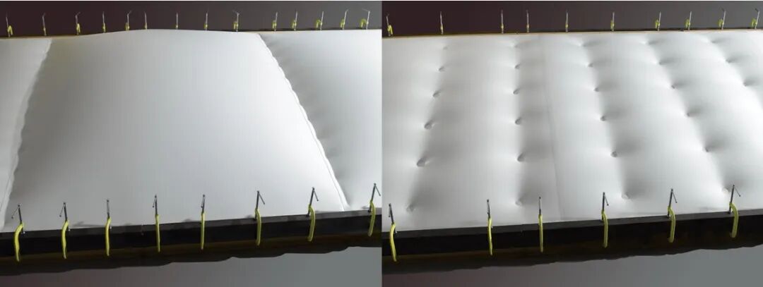
Figure 1. Comparison of wind load stress tests with and without perforations (left) and right.
The non-perforated mechanical fastening system has the following advantages:
1) This process does not penetrate or damage the roofing membrane, effectively ensuring its integrity and reducing the risk of leakage;
2) The non-perforated fasteners are more evenly distributed, making the stress on the single-layer roofing membrane more reasonable and increasing its wind load limit;
3) Due to the even distribution of the fasteners, the membrane adheres more tightly to the base layer, effectively reducing membrane swaying and the resulting wear or even damage;
4) The roof corner reinforcement area no longer requires cutting the membrane for reinforcement, reducing overlap and correspondingly reducing the risk of leakage;
5) Unified fixing with the insulation layer can reduce the number of fasteners by 20% to 50%, while reducing damage to the steel plate structure, thus better ensuring the safety of the system.
1.3 Principle of Non-Perforated Welding Process
The non-perforated mechanical fastening process uses specialized non-perforated fixing gaskets, along with screws, metal strips, and other supporting materials, to directly fix the insulation layer, TPO waterproof membrane, and other layers to the metal roof base or structural purlins (Figure 2 shows its roof system structure). The process works by using heat generated by electromagnetic induction in the heater to heat the membrane while simultaneously welding a special coating on the lower metal gasket to the membrane. A magnetic cooling tool is then placed on the heated area, attracting the metal gasket to its bottom. This cooling process simultaneously strengthens the weld and achieves a non-perforated fixation. The fasteners must be installed and fixed together with the insulation layer.

Figure 2. Construction of TPO single-layer roof non-perforated mechanical fastening system
2. TPO waterproof membrane non-perforation mechanical fastening process
2.1 Equipment Preparation
1) TPO Laying: Fixing and sealing strips, welding ropes, weather-resistant sealant, automatic welding machine, handheld welding torch, etc.
2) Non-perforated Welding: Non-perforated welding machine, non-perforated gaskets, gasket sleeves, fixing screws (passed 1000h salt spray test). Figure 3 shows the TPO non-perforated welding machine on the left and the fixing components on the right.

Figure 3. TPO non-perforated fastener and welding machine
2.2 Construction Process Flow

2.3 Specific Operations and Precautions for Non-Perforation Construction
2.3.1 Substrate Preparation Before construction, inspect the roof substrate to ensure the roof installation is secure, durable, free of rust and cracks, and remove loose particles, holes, sharp protrusions, or other debris that may obstruct the entire system.
2.3.2 Vapor Barrier Installation This project uses a PE film material with sufficient strength and strong vapor barrier properties as the vapor barrier to prevent water vapor penetration. The overlapping edges and areas around joints of the PE film are sealed and fixed with butyl waterproof sealant tape. In previous projects, lightweight non-woven fabric was used as the vapor barrier, but its insufficient strength led to easy damage, and it was not effective at blocking water vapor, causing the insulation layer to become damp, resulting in poor performance. Therefore, its use is not recommended.
2.3.3 Insulation Layer Laying and Fastener Installation
The insulation layer in this project uses 1.2m × 0.6m rock wool boards. Referring to JGJ/T 316—2013, each board must have at least two fasteners (see Table 2 for a comparison of the number of fasteners required for rock wool boards and other insulation boards), arranged along the longitudinal centerline. Ensure the substrate is dry before installation. For layered insulation boards, stagger the joints to prevent through-joints, and ensure tight joints. If necessary, fill any gaps with similar materials to avoid cold bridging.
The insulation layer and roofing membrane are uniformly fixed using dedicated non-perforated fasteners. The location and quantity are arranged according to the detailed design. Before drilling, a grid pattern is marked on the insulation layer for positioning. Pre-drilling and pull-out tests are performed before fixing to ensure the pull-out force of the screws on the metal substrate meets the specifications. Fasteners are fixed on the crests of the profiled steel sheet and perpendicular to the roof panel. After the non-perforated gasket is fixed, it should be parallel to the surface of the insulation board. The gasket should not be fixed too deeply into the insulation layer, and it should not be tilted too much to facilitate subsequent gasket welding operations.
Table 2 Quantity and Location of Fasteners for Plate-like Thermal Insulation Materials

2.3.4 Waterproof Membrane Pre-laying
When pre-laying the waterproof membrane, first, naturally unfold the membrane onto the completed insulation layer, ensuring it is flat and straight to release stress and reduce wrinkles. Cut it appropriately according to the actual site conditions to ensure the overlap width and staggered joint requirements.
2.3.5 TPO Waterproof Membrane Non-perforated Welding Process
Non-perforated welding machine start-up procedure: Confirm that the voltage regulator is connected to the power supply and that no other machines are connected to the equipment; after the power supply is stable, connect the non-perforated welding machine power cord to the equipment and start a test weld.
During the test weld, cut a piece of membrane and a gasket and lay them loosely on a flat surface. Weld the membrane to the gasket according to the instrument operating specifications. Then, place a magnetic radiator on top of the welded gasket for cooling and to reinforce the weld strength. Place the radiator on the welded gasket for at least 45 seconds. After the welded surface has completely cooled, remove the membrane for a peel test to check the weld's adequacy. If the ambient temperature change exceeds 5°C, repeat the test weld.
After trial welding, welding of the fasteners without perforations begins in the reinforced areas such as corners and edges, followed by welding in the non-reinforced areas. Generally, the membrane is welded strip by strip according to its laying direction. The magnets in the cooler will attract iron slag and other impurities; therefore, the bottom surface of the cooler needs to be inspected before each construction session, and any impurities should be cleaned promptly.
2.3.6 Welding of Large-Area Joints of Waterproof Membrane
Welding of the long-side overlaps of the membrane is performed using an automatic welding machine, while short-side overlaps and detail treatments are welded using a handheld welding gun. The overlap width for non-perforated systems is generally 80 mm.
Machine welding is mainly used for welding the long sides of large-area membranes. The procedure is: adjust the membrane overlap width—set welding parameters—preheat the welding machine—weld—weld inspection.
Handheld welding gun welding is mainly used for welding the short sides of the membrane and for detail treatments. The procedure is: adjust the membrane overlap width—set welding parameters—preheat the welding gun—spot welding—pre-weld—final welding—weld inspection.
When welding T-shaped overlaps, the welding machine must be pressurized to ensure a tight weld. A homogeneous circular sheet should be used for repair and reinforcement to prevent incomplete welds and through-seams that could lead to leaks.
The roofing membrane and insulation layer laid on the same day must be welded on the same day. Any unfinished sections left after each day's work should be protected with tape and effective rainproofing measures to prevent rain and moisture damage.
2.4 Specific Operations and Precautions for Non-Perforated Construction
2.4.1 Detailed Treatment of Waterproofing Membrane The main roof waterproofing surface uses fabric-reinforced (P-type) TPO membrane. Since P-type membrane incorporates a fabric mesh within the TPO sheet, the fabric mesh does not provide waterproofing without special treatment. Therefore, we simulated a riser model with a core of P-type TPO waterproofing membrane, approximately 8 cm wide, and about 10 cm of water accumulation. After about 10 minutes without any pressure, significant water seepage occurred (Figure 4). Given the characteristics of P-type TPO waterproof membrane, and the fact that cutting is unavoidable when using TPO waterproof membrane, this project uses homogeneous H-type material or covering strips to treat or cover the short edges of the cut membrane at detailed joints or when using it to reduce the risk of leakage.

Figure 4. Leakage risk test of P-type TPO
2.4.2 Parapet Wall Finishing
At the parapet wall finishing area, TPO waterproof membrane is laid to the appropriate upturned finishing area on the facade. H-type TPO membrane is used to adhere the facade with adhesive. The upper end of the finishing is fixed with a pressure strip and sealed with sealant (Figure 5).

Figure 5 Recommended method for finishing the parapet wall with an upward turn.
If the parapet wall is low, to improve the reliability of the sealing and reduce the risk of leakage, the H-type roofing membrane can be folded up to the outside of the parapet wall before being fixed with a sealing strip, and then completely covered with a special aluminum composite panel. This method provides better waterproofing. This is offered for reference by industry peers.
2.4.3 Special Reinforcement Treatment for Internal Gutter Tie Rods In past projects, when welding tie rods, only the edges of homogeneous TPO roofing membrane were heated and welded to the main surface. Furthermore, to reduce the risk of leakage, the weld seam often needed to be left facing downwards beforehand, making welding difficult and the weld quality hard to guarantee.
To address the above challenges, an additional annular homogeneous TPO reinforcing layer was installed on-site, spot-welded to the roofing membrane of the gutter. The weld seam of the membrane at the tie rod body could then be positioned directly above for easy welding. After the tie rod body welding was completed, the extended edge of the tie rod membrane was stretched and sealed to the annular reinforcing layer. After the membrane welding at the tie rod was finished, the spot-welded portion of the annular reinforcing layer was pulled apart, and the weld seam, along with the tie rod membrane, was rotated to the bottom of the tie rod before being welded to the roofing membrane of the gutter (Figure 6). This method proved effective in the field, reducing welding difficulty, ensuring weld quality, and minimizing the risk of leakage.

Figure 6. Example of adding a ring-shaped reinforcing layer to the eaves gutter tie rod.
2.4.4 U-shaped strip protection
To prevent the U-shaped strip from being too sharp and puncturing the roll material, a small piece of roll material is cut on-site and welded to wrap around the sharp part of the strip edge for protection (Figure 7).

Figure 7 Example of U-shaped pressure bar welding protection operation